Team RC17 - technical My pithy slogan tag:teamrc17.net,2005:3424574579b43e942f2d347e959d0bf3/technical Textpattern 2020-09-07T08:55:19Z Michael mike@brendies.net http://teamrc17.net/ Michael 2012-08-12T14:18:26Z 2012-08-12T14:41:37Z RC24 Wheel Conversion tag:teamrc17.net,2012-08-12:3424574579b43e942f2d347e959d0bf3/9783f871d4a8b1090ce4016772ebda0d Photographs, text and words by Mr_T, pictures scanned and massaged by Viking.

First, a quote from John Robinson in his “Motorcycle Tuning: Chassis” book:

“The wheels and various things attached to them are critical to the bike’s performance. The masses of these parts have rotating inertia which has to be increased or decreased whenever the bike is accelerated or braked: it is unsprung mass, and therefore governs how the suspension performs; it is steered mass which affects the steering response and creates gyroscopic forces which interact with the steering. Every pound of material carried on the wheels is worth two to five pounds carried elsewhere on the bike”

Why Comstars?

The Comstar wheels fitted to the RC17 are a combination of rolled sheet alloy and a cast alloy hub. The rim is attached to six sheet alloy “spokes” with 12 rivets. The spokes are attached to the hub with six special-headed nuts and bolts to reduce tampering.

Comstars of various sizes were fitted to many different Hondas, from CB250s to the CB1100Rs, before the one piece cast alloy wheels that we take for granted today were common. Comstars are very similar in concept to the UK made “Astralite” wheels of the 1980’s. Which came first? I don’t know, but it would be interesting to know.

The Comstar has some advantages over conventional spoked wheels:

  • Less individual bits to assemble at the factory
  • Handle tubeless tyres
  • Don’t lose spoke adjustment
  • Fairly stiff for their mass

Why RC24 one-piece cast alloys instead?

The one-piece wheels are an integrated structure, there are no rivetted or bolted joins so the spokes and the rims are more stiffly connected to the hub. All of the braking, accelerating and cornering forces are more widely distributed over the hub/spoke join.

I chose the 1986 RC24 wheels because their rim diameters and tyre sizes are compatible with the RC17. As well, the disc flange dimensions are the same so my RC17 discs bolt straight on to the RC24 flanges, front and back. The RC24 uses the same wheel bearings, and the RC17 sprocket carrier drops straight in, cushions and all.

Apart from that, I’ve measured the RC24 wheels to be a bit lighter than the Comstars they replace, which would result is some small performance benefits. The front wheel is about 4.4kg – about 0.2kg less than the front Comstar. The rear wheel is about 6.1kg – about 0.4kg less than the original Comstar. That doesn’t sound like much, but when the wheels are spinning on a bike doing 200kmh, I think I will notice the difference. These weights include the bearings, internal spacer, seals and air valve, but not disc(s) or tyre.

For the curious among you, the complete RC24 rear wheel with all spacers (including rear caliper carrier), axle, bearings, sprocket carrier, sprocket, disc, valve, tyre, seals and 38psi air weighs 19.3kg.

The complete RC24 front wheel with spacers, axle, bearings, seals, speedo drive, two discs, bolts, valve, tyre and 35psi air weighs 12.6kg.

RC24 wheels are a lot easier to clean than Comstars! RC24 wheels still have their share of nooks and crannies to hold dirt, but they are still more accessible than the Comstar sheet spokes. Take it from me, to really clean a Comstar properly, you have to remove the wheel from the bike and strip it of discs and bearings before getting onto it with degreaser. I’ve done this, and removed the tyre as well just to make it easier to handle.

RC24 wheels are a bit wider than the Comstars. While the RC24 had tyres of the same specified size as the RC17, the RC24 rim widths are closer to ideal width for the specified tyres.

Who did the conversion?

Bob Martin Engineering, 18 Kevin Avenue, Ferntree Gully 3156. Phone +61-03-9758-4738.

What’s involved in the conversion?

Rear: practically nothing, drops right in from what I could see.

Front: here is where is gets interesting and where Bob Martin’s earned their money, the RC24 discs mount a bit under 10mm closer together than the RC17. Therefore, to align the discs up with the calipers on the RC17 forks, either the discs had to be spaced further apart or the calipers moved inward toward each other. It is a lot easier to space the discs apart than to alter the caliper mounts on the forks or adapt the calipers.

Note: the brakes generate very large forces, most bikes will decelerate under brakes faster then they can accelerate with the engine, traction and centre-of-gravity being the main limitations. For example: if your 70hp bike can accelerate from 0 to 100kmh in 4 seconds, and can stop from 100kmh to 0kmh in 4 seconds, then your brakes are doing 70hp of work on the forks and discs and wheels. That’s 70hp being transmitted through the disc bolts and caliper mounting bolts and into the forks. You’ve got to get the forces in the brake system right or you’ll be in trouble, sooner or later. “Motorcycle Tuning: Chassis” explains it and many more things better than I can.

Yeah yeah, where are the pictures?

Right here:

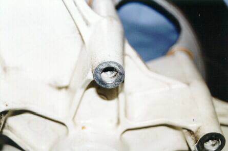
The standard RC24 front disc mounting point

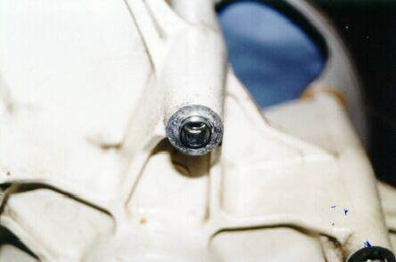
One of the fabricated collars inserted

The spacer goes over the collar

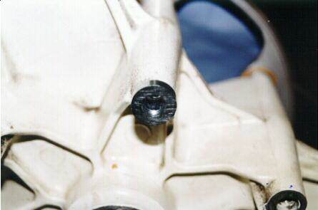
Fully assembled with disc and bolt, note the small paper “dampimg shim” between the disc and the spacer. These shims are $1.80 each from Honda.

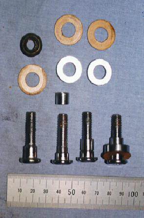
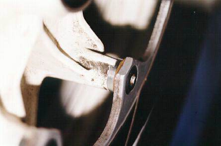
At left is a standard RC17 bolt, shim and nut. The RC24 doesn’t use a nut, the bolt goes straight into the hub casting and is also shorter than the RC17 bolt.
Second from the left if the modified bolt, a collar, a spacer and shim. Note how the shoulder on the bolt has been machined down to take the collar, which is the same diameter as the shoulder. It’s not the threaded part of the bolt that transfers the braking torque to the hub, it’s the shoulder.
The rightmost bolt shows how it fits together. It looks simple enough, but the spacer has to be precisely machined to make sure the disc doesn’t warp when fitted and create uneven braking.

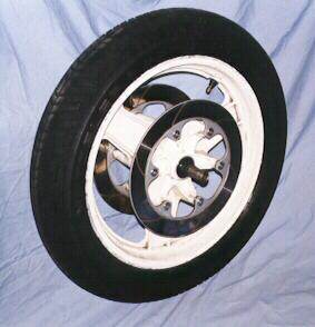
The finished front wheel before it was mounted on the RC17

The finished rear wheel before it was mounted on the RC17

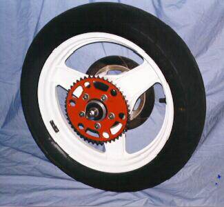
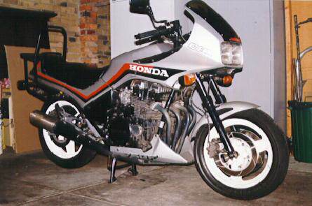
The finished product, possibly the only RC17 in the world with one piece cast alloy wheels. I think the white wheels look awful. I expect to have the wheels re-coated in black or dark grey to give it a “factory” look.

What did it cost?

The pair of RC24 wheels were $450 from Bikes and Bits (Original), 659 Nepean Highway, Brighton East, +61-03-9592-3366.

Bob Martin charged $200 for the front and $50 for the rear. This included changing over bearings, tyres and discs to the new wheels and the fabrication of the spacers and modification to the disc mounting bolts.

Errata:

When list member Andy attempted the same conversion, he found that there were two different sets of rims. For his comments on how he resolved the issue, read this article.

You may also need his engineering drawings of the pieces he had to make.

]]>
Michael 2010-04-20T17:52:01Z 2010-04-20T17:56:41Z Rear Shock Fluid Replacement - RC17 tag:teamrc17.net,2010-04-20:3424574579b43e942f2d347e959d0bf3/29b9dd24be429e7804e2bd40cca3010f The article below based on the similar VF1000 model equipment inspired me to replace the damping fluid of my RC17 rear shock. I followed the procedure generally as recorded except:

  1. Expel the existing fluid by using a large plastic syringe (60ml?) whose end happened to be exactly the correct size to screw into the hose after the valve was removed. A couple of pumps of air were enough to encourage the fluid to come out quickly into the syringe. I left it overnight to drain the remnants into the measuring beaker – and got 340 ml.
  2. To fill I set up the shock vertically with the hose at the top and used the syringe to inject the ATF from its measured amount into the hose – much quicker than waiting for it to drain in under gravity.
  3. For both of these pumping operations you need to allow the excess pressure to escape, but this can be controlled by opening the syringe to accept it.
  4. I chickened out of removing the hose from the body – but I do not see why this could not be done to further aid the operation. Perhaps the hole would not be the correct size for the syringe end, and resealing may be awkward.

I can’t claim any great difference in feel on the bum-ometer, but at least I know it’s all clean inside. Don’t forget to re-pressurise the shock after re-installation.

—-SRM—-

Rear Shock Fluid Replacement – VF Series

From http://www.one-ring.net/vfrfaq/general.html#absrep

by: Joe Thorne – Foreword by Christopher Leach

With the shocks in our bikes getting on in years, some folk have begun to experience significant sagging and less than desirable damping characteristics in their shocks. Unfortunately, Honda designed this shock as a ‘non-rebuildable’ shock. This means that the spring is sealed inside the shock and cannot be replaced. However, it is possible to get a few more miles out of them by improving the damping and increasing the air pressure (preload). The following procedure details replacing the shock oil with heavier fluid for improved dampening characteristics. (Editor)

I have never seen a rear shock leaking, but the service manual details how to change the seal. IMHO, if the seal is leaking, get a new shock. If you want to change the fluid, however, the manual still wants you to replace the seal. Ten years as a flat-rate tech, I sure as hell aren’t changing a seal that isn’t leaking.

Tools needed:
Whatever you need to pull the shock
Graduated beaker
Funnel small enough to screw on the airline for your shock

So the best and fastest way to replace the fluid is to remove the shock. (See your service manual).

Once you pull the shock out, unscrew the Schrader valve from the hose. (The valve screws on the line at the end, 10mm and 12mm hex heads.)

Hold the shock at a 45 degree angle over the graduated beaker, with the valve and hose facing down. You will have to wiggle it back and forth a little to get all of the fluid out. The reason to drain into the beaker is this: My manual called for 300cc of fluid, I got 340 out.

I replaced the crap that came out, which was smoked ATF, with ATF. In hindsight, I would use 15wt fork oil.

To replace the fluid, take your funnel and seal it to the air fill hose. I nailed the funnel to the workbench, and set the shock on the floor.

However you do it, make sure the funnel is well supported as high as possible. I filled the funnel and walked away. Twelve hours later, I walked into the garage to see the last of the fluid drain out into the shock. I kept a small space heater on the shock to keep the fluid as thin as possible.

(Editor’s note: When I did this, I used 340 cc of 10WT fork oil. In retrospect, I too would use 15W for a little stiffer ride. Some listers have reported using 30W with no seal problems.

Also, I used an irrigation syringe to force oil into the open hole in the shock body.

Only took about 30 mins. The author’s bike is a VF1000R, editor’s bike is an ’84 VF1000F Interceptor)

]]>
Michael 2010-04-15T23:57:25Z 2016-02-04T19:17:50Z Wiring Diagrams tag:teamrc17.net,2010-04-15:3424574579b43e942f2d347e959d0bf3/237fc302549453e4dcc9a55a37b25238 For those of you who need a wiring diagram of the RC17, here it is!!

CBX Wiring

List member Roddy has sat down in front of his computer, and created this beauty: a coloured version of the wiring diagram picture.

CBX Wiring Coloured

Another handy reference chart – a list of what wire colour does what, and connects which switch to what output.

Wiring Colours

]]>
Michael 2010-04-15T23:20:20Z 2010-04-15T23:41:54Z Electrical System Modification tag:teamrc17.net,2010-04-15:3424574579b43e942f2d347e959d0bf3/926170f8e70e454a899f5001bb52a1db Some CBX750s suffer problems with the electrical system, the voltmeter reads anywhere between 14 and 16 volts, and with the headlights off it nearly always is sitting on 16v and some even with the headlights on. The manual says that anything over 15v indicates an electrical overload.

As far as the group has been able to determine, this problem is due to the regulator incorrectly reading the battery voltage. After going all the way through the loom and back to the regulator, the added resistance of the loom causes the regulator to believe that the battery is 1 volt below the true battery voltage.

This can cause 2 problems. First the battery is constantly being charged and this shortens the life of the battery. Second, fuses blow for no apparent reason or your headlights blow more frequently than they should. My CBX went through 5 in a year.

The solution however is relatively simple. We provide a short-cut so that the regulator sees the correct battery voltage, direct from the battery; rather than the incorrect voltage from the loom. We use a relay to stop the battery being drained by the regulator.

You will require a standard headlight electrical relay , a couple of short pieces of wire (4 × 18” pieces will be fine for under seat installation and 4 × 8” pieces for under side cover installation), a selection of wire connectors, a soldering iron and wire cutters.

For the brave (or those who simply want to see what we’re doing), here’s the schematic diagram:

  • Disconnect the battery. (Only the positive lead really needs to be removed)
  • Remove the seat and the left hand side cover
  • Locate the connector block that is connected to the regulator.
    It is the one on the right of the bracket attached to the airbox with only 3 wires going to it.
    A Black, Green and a Red/white

  • Disconnect the block and remove the black wire as shownabove.
    This is a small spade connector and is held into the block by a small tang that comes off the spade itself and can be removed by inserting something sharp into the bottom of the block and depressing the tang, this will allow the removal of the spade.
  • You need to cut the black wire (this is the only wire that need to be cut) and strip the end of the wire. You need to connect a extension onto this wire and I suggest soldering it rather than one of those crimp connectors as this provides a more permanent and better connection.

In Image 2 you can see we have elected to extend the wire by using connectors rather than cutting and soldering. This was done because we only had my bike as a test and it seemed to work there but when I start working on someone else’s bike I tend not to make assumptions and wanted to be able to reverse the installation completely. The wiring here is from Viking’s bike which was suffering from the 16volt syndrome before we started.

Note the picture displays the black wire connected to a Yellow/Red wire. Really you should not do this, try to use the same color wiring.

  • Remove the Red/white and Green wire from the block also as displayed in Image 2. We need to connect a wire to each of these that will run to the relay.
    This is how we connected them again so that the project was reversible, If you connect the extensions as seen here the spades will go back into the block without any problems. Connect a female spade connector to the end of each of these wires.
    The image here was taken from above the bike, looking down at the wires, so the orientation of the wires may appear slightly strange.
  • Assemble the final piece of wire that you have with a male spade connector on one end and a female connector on the other.

  • Reassemble the block .
    Pay attention to the color of the wires on the regulator side of the connecting block as these need to match the colors of the wires in the top block
    Do not connect the black wire to the block as this will go to the relay.
    That spare wire you have goes into the block in place of the black wire.
  • Connect the extension wire from the Green lead on the block to pin 86 on the relay.

Connect the extension wire from the Red lead on the block to pin 87 on the relay.
Connect the Black lead from the loom to pin 85 on the relay.
Connect the new piece of wire to where the black wire was on the connector block and to pin 30 on the relay.
This is an image of a completed assembly using all the right colored wires.

Just to show you that we can do it the right way.
This unit was mounted under the Side Cover.
Here you can see that Viking elected to have his under the seat.
List member Alan has come up with an interesting solution to the problem – rewire the bike! Or at least parts of it. I won’t bore you with the details, but by adding larger wires and additional ground paths, Alan has solved the problems he was having with low voltages and bad grounds. View the details here in his write-up (28KByte Adobe Acrobat file).

]]>
Steve Oxley 2009-10-28T03:30:24Z 2009-10-28T03:30:24Z Update: October 28th, 2009 tag:teamrc17.net,2009-10-27:3424574579b43e942f2d347e959d0bf3/dab0075ab28f5dfa1275767a721815d9 I’ve been asked to provide an update to how the EFI project is going.

In a nutshell, it hasn’t gone anywhere at all since my last update. The bike has been parked at a friend’s house for the last 3 years – he needed a bike to ride whilst his was being fixed. Luckily for me, he starts it up and lets it run for 5 or 10 minutes every 6 months or so. Luckily for him, he has very understanding neighbours!

Overall, the EFI is running too rich – dropping the amount of fuel by about 10% should sort that out easily. The MegaTune software that I was using allows you to do that quickly and easily. (It’s a simple matter to change the ‘ReqFuel’ variable or the injector open duration. From memory, it’s currently set to 5.5 milliseconds. Dropping to about 4.9 should sort things out.)

Around town, it’s not that good – it doesn’t want to idle properly, and the quick-action throttle makes it difficult to open the throttle a small amount. The revs surge up and drop back until repeatedly until they fall too low for the engine to run (and then it stalls). I had to reach down to the throttle bodies and manually turn cable attachment by hand. Even then it’s a tricky job to get it right.

I think that could be fixed by redesigning the throttle stop so that the throttle is held open a little bit more, and perhaps a bit of a tweak to the lower-end of the fuel map.

Once you get moving, it’s fantastic. Not a lot of power below about 5,000 RPM (kind of like the stock CBX). Once you open it up, however, it’s a different story. The tacho needle rips towards the redline at a great rate of knots, the exhaust howls in your ears, and the horizon leaps at you.

I didn’t get a dyno run, and I really wish I had. A ‘before’ and ‘after’ comparing the carbs to the EFI power output would be fantastic to see. I estimate that the carbs were giving me about 80 to 85 horsepower at the rear wheel, and the EFI is easily more than that.

]]>